From:Taian Haishu Machinery Co.,Ltd. Updatetime:2026/9/7 9:50:11 Views:
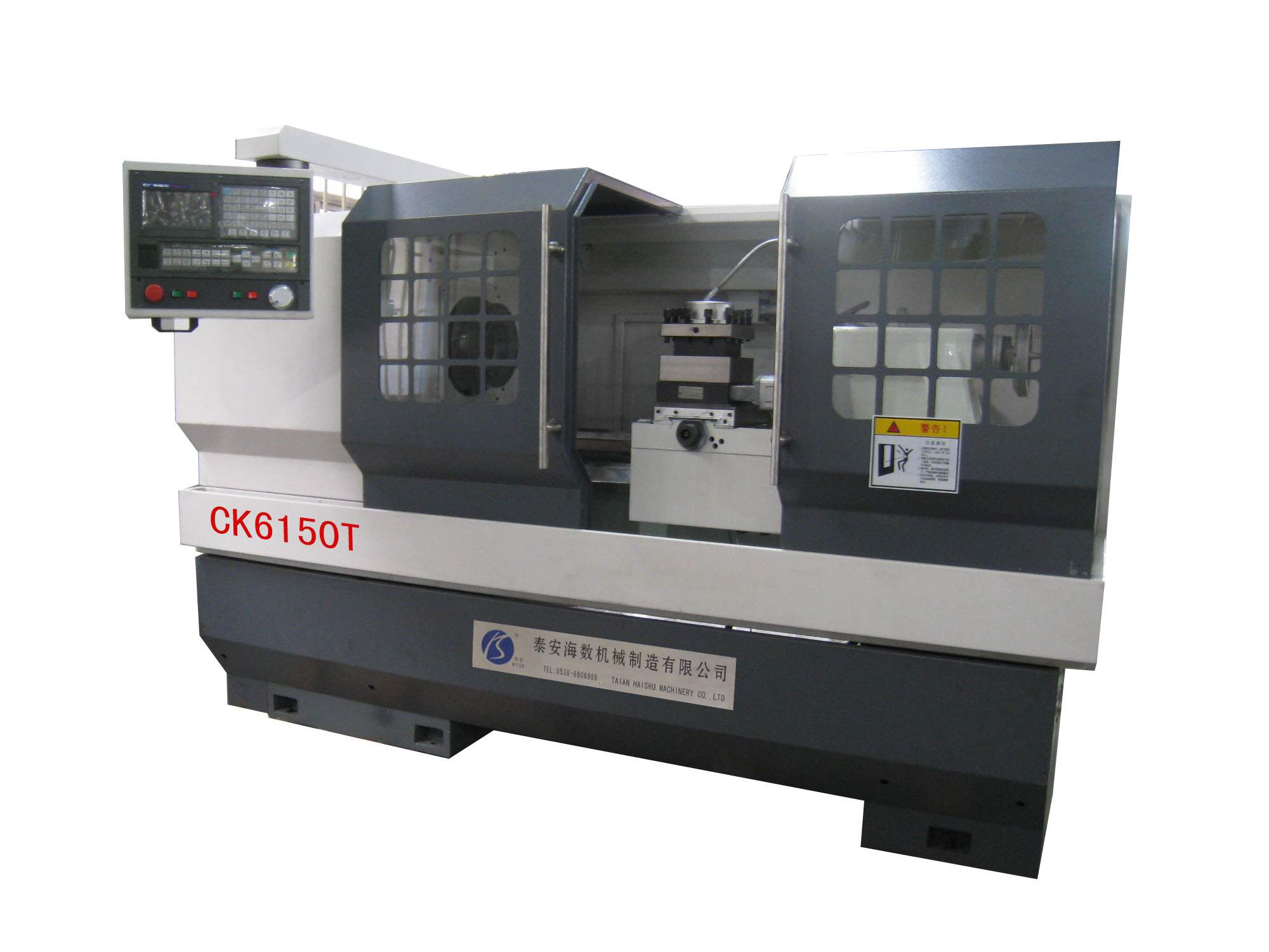
In CNC lathe machining, the synergistic optimization of cutting tools and cutting parameters is key to balancing machining efficiency, cost, and quality.
In CNC lathe machining, the synergistic optimization of cutting tools and cutting parameters is key to balancing machining efficiency, cost, and quality. An unsuitable combination of parameters can lead to rapid tool wear, workpiece scrapping, or even equipment damage.
This approach addresses two dimensions—tool selection and cutting parameter optimization—aiming to provide a systematic reference framework.
I. Tool Selection: Precise Matching is the Prerequisite for Efficient Machining
CNC lathe machining involves consolidated processing steps, placing higher demands on the comprehensive performance of cutting tools. Tool selection should adhere to the principles of high precision, high reliability, high durability, and excellent chip-breaking and chip-removal capabilities.
1. Selecting Tools Based on Workpiece Material
The physical properties of different materials dictate the choice of tool materials and geometric parameters.
| Workpiece Material |
Recommended Tool Material |
Key Geometric Parameter Recommendations |
Notes |
| Aluminum Alloy |
HSS, Coated Carbide, PCD (Polycrystalline Diamond) |
Large rake angle (15°–25°) |
Good thermal conductivity; high cutting speeds can be used |
| Ordinary Steel/Carbon Steel (e.g., 45# Steel) |
Carbide (Coated or Uncoated) |
Rake angle of 5°–15° |
Most common combination; wide range of parameter choices |
| Stainless Steel/Titanium Alloy |
Wear-resistant carbide, tools with sharp cutting edges |
Large rake angle, sharp cutting edge |
Prone to work hardening; requires good heat dissipation and cooling |
| Hardened Steel (HRC 45+) |
CBN (Cubic Boron Nitride), Ceramic tools |
Negative or small rake angle to enhance edge strength |
High brittleness; unsuitable for interrupted cutting |
| Cast Iron |
Carbide (e.g., YT grade), Ceramic tools |
Cutting speed should not be too high |
Surface may have a hardened skin; initial cut depth must be sufficient |
2. Selecting Tools Based on Machining Stage
Rough machining and finish machining have vastly different requirements for tools.
- Rough Machining: The core objective is efficient material removal. Prioritize tools with high strength and durability. Regarding geometry, consider using a negative rake angle (to strengthen the edge), a large major cutting edge angle, and a large nose radius (e.g., R0.8). Square or rhombic inserts are suitable due to their higher strength.
- Finish Machining: The core objective is ensuring dimensional accuracy and surface quality. Select tools that offer high precision and sharp cutting edges. Regarding geometric parameters, a positive rake angle (to reduce cutting force), a small major cutting edge angle, and a small nose radius (e.g., R0.2–R0.4) are adopted. Triangular inserts may be selected for cost-effectiveness.
3. Key Points for Selecting Tool Geometric Parameters
- Rake angle: Affects cutting force and cutting edge strength. Use a positive rake angle for machining ductile materials (such as aluminum alloys) and a negative rake angle for hard, brittle materials (such as hardened steel).
- Clearance angle: Affects friction and cutting edge strength. Use 6°–8° for rough machining and 8°–12° for finish machining.
- Major cutting edge angle: Affects the distribution of cutting forces. Common angles include 45°, 75°, and 90°.
- Nose radius: Affects surface roughness and cutting force. Select a large radius (R0.8) for rough machining and a small radius (R0.2–R0.4) for finish machining.
II. Optimization of Cutting Parameters: Finding the Optimal Balance Between Efficiency, Quality, and Cost
The three key cutting parameters—cutting speed (Vc), feed rate (f), and depth of cut (ap)—are variables that directly influence machining efficiency, tool life, and workpiece quality.
The core principle of optimization is: prioritize efficiency for rough machining and prioritize quality for finish machining.
1. Logic and Reference Values for the Three Key Cutting Parameters
(1) Cutting Speed (Vc)
Setting Logic: Vc has the greatest impact on tool durability. Increasing Vc can shorten machining time but drastically reduces tool life. For example, a 20% increase in cutting speed could cut tool life in half.
General Reference Ranges (Carbide Tools):
| Workpiece Material |
Rough Machining Vc (m/min) |
Finish Machining Vc (m/min) |
| Low/Medium Carbon Steel (e.g., 45# Steel) |
80 - 120 |
120 - 200 |
| Alloy Steel |
60 - 120 |
100 - 180 |
| Cast Iron |
70 - 80 |
80 - 200 |
| Aluminum Alloy |
- |
300 - 1000 |
Note: Specific Vc values should be based on parameters provided in the tool manufacturer's catalog and adjusted according to actual conditions, such as machine tool rigidity and workholding stability.
Spindle Speed Calculation Formula:
n = (Vc × 1000) / (π × D)
Where n is the spindle speed (r/min), Vc is the cutting speed (m/min), and D is the cutting diameter of the workpiece (mm).
(2) Feed rate (f)
Setting logic: Feed rate directly affects surface roughness. For rough machining, select a higher value—provided tool strength allows—to increase efficiency; for finish machining, select a finer value based on surface roughness requirements.
General reference ranges:
Rough machining: 0.1 – 0.3 mm/r
Finish machining: 0.05 – 0.1 mm/r (use 0.06–0.12 mm/r for high surface quality requirements)
Special operations (parting-off, deep-hole machining): Use lower values
(3) Depth of cut (ap)
Setting logic: Depth of cut determines the number of passes. For rough machining, select the largest possible value—within the limits of machine power and the rigidity of the machining system—to remove the bulk of the material allowance in a single pass; for finish machining, use a smaller value to ensure dimensional accuracy.
General reference ranges (radial depth of cut):
- Rough machining: Generally not exceeding 5 mm (for medium-power machines cutting 45# steel); maximum can reach 8–10 mm
- Semi-finish machining: 0.5 – 5 mm
- Finish machining: 0.1 – 0.5 mm (use 0.1–0.3 mm for extremely high requirements)
Calculation formula: ap = (Dw - Dm) / 2
2. Impact of cutting parameters on tool life
Understanding the relative impact of these three factors on tool life helps in quickly identifying and troubleshooting issues:
- Cutting speed (Vc): Has the greatest impact. Excessive Vc is the primary cause of reduced tool life.
- Feed rate (f): Has a moderate impact. Excessive feed rates accelerate flank wear.
- Depth of cut (ap): Has a relatively minor impact; however, if it is too shallow, "rubbing" rather than cutting occurs, creating a work-hardened layer that actually reduces tool life and degrades surface quality.
III. Comprehensive Optimization Strategy: An Example Involving a 45# Steel Part
Scenario: A part made of 45# steel (quenched and tempered to HRC 28–32) requires an M105×2 thread. The original process used a spindle speed of 800 r/min, but each cutting edge could only machine 8–10 parts, resulting in severely inadequate tool life.
Problem Diagnosis:
Calculate the cutting speed (Vc) of the original process: Vc = π × 800 / 1000 ≈ 251 m/min.
For 45# steel quenched and tempered to HRC 28–32, a reasonable Vc is approximately 120 m/min. The original Vc was too high, causing a drastic reduction in tool life.
Optimization Strategy:
- Reduce cutting speed: Lower Vc from 251 m/min to 120 m/min. Recalculate spindle speed: n = (120 × 1000) / (π × 105) ≈ 364 r/min.
- Adjust feed rate: Threading is a specialized machining operation; the feed rate must be set based on the thread pitch (2 mm) to ensure the feed per revolution precisely matches the pitch.
- Projected outcome: Adjusting the cutting speed to an appropriate range will significantly extend tool life, with an expected increase from 8–10 parts to 15–20 parts per cutting edge (reaching the standard service life specified in the tool manufacturer's data).
IV. Summary and Implementation Recommendations
Selecting tools and optimizing cutting parameters for CNC lathes is an engineering challenge that requires a systematic approach.
- Establish a "Material-Tool-Parameter" matching chart: Compile common workpiece materials, corresponding tool models, and recommended cutting parameters (Vc/f/ap) into internal standards to serve as a basis for programming and operation.
- Follow the "Roughing Before Finishing" sequence: For roughing, determine *ap* first (maximize it), then *f* (maximize it), and finally *Vc* (balancing for tool life). Reverse this order for finishing: determine *ap* first (based on stock allowance), then *f* (based on surface roughness), and finally *Vc*.
- Use tool manufacturer data as a baseline: Parameters provided in tool catalogs serve as a crucial starting point; adjustments should be made based on these figures while considering actual shop-floor conditions.
- Consider the economics of tool life: Cost per part = Tool cost / Number of parts produced. Sometimes, selecting a tool with a higher unit price but longer service life (such as coated inserts or CBN tools) results in a lower overall cost.
- Leverage modern optimization tools: For critical components or high-volume production, employ scientific methods—such as orthogonal testing or genetic algorithms—to systematically identify the optimal combination of parameters.
As a professional CNC lathe manufacturer, Haishu Machinery not only provides high-rigidity equipment platforms but is also committed to sharing advanced machining techniques and expertise in parameter optimization. If you encounter machining challenges with specific parts, you are welcome to consult with Haishu Machinery’s technical team.